2.0 CUDA Programming Model Overview (Part I)
2018-02-15 | CUDA , Freshman | 0 |
Abstract: This article introduces the basic structure of the CUDA programming model, including writing a simple executable CUDA program, a correct CUDA kernel function, and the corresponding adjustments for setting up memory and threads to run the program correctly. Keywords: CUDA Programming Model, CUDA Programming Structure, Memory Management, Thread Management, CUDA Kernel Function, CUDA Error Handling
CUDA Programming Model Overview (Part I)
The programming model tells us how to write CUDA programs. If you've done C development or other development work, you know that a complete project isn't just about writing code -- there's also requirements analysis, debugging, optimization, deployment, and a series of other steps. The CUDA platform also provides this suite of tools for us to use. This chapter mainly explains how to use these tools, how to write and debug CUDA programs, and includes writing two matrix operation CUDA applications for you to experiment with.
CUDA Programming Model Overview
The CUDA programming model is the bridge between applications and hardware devices. CUDA C is a compiled language, not an interpreted language (OpenCL is somewhat similar to an interpreted language). Through compilation and linking, it's executed by the operating system (which includes the GPU as part of the system). The following diagram vividly illustrates their relationships:
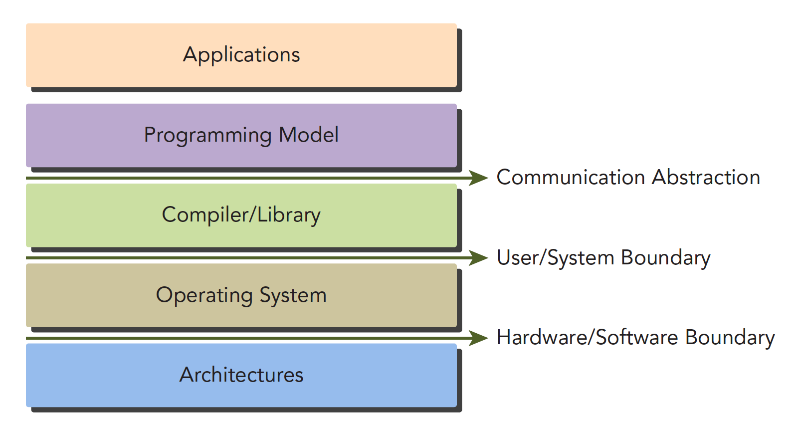
The Communication Abstraction is the dividing line between the programming model and the compiler/library functions.
You might not fully understand what a programming model is yet. Think of it as the syntax, memory structure, thread structure, and other parts that we control when writing programs. These parts control the working mode of the heterogeneous computing device -- they all belong to the programming model.
CUDA programming can roughly be divided into:
- Kernel functions
- Memory management
- Thread management
- Streams
These are the key components.
The above theories also apply to other non-CPU+GPU heterogeneous combinations.
Below we'll discuss two features specific to GPU architecture:
- Methods for organizing threads on the GPU through organizational hierarchies
- Methods for organizing memory on the GPU through organizational hierarchies
In other words, controlling memory and threads will accompany us through the first dozen or so articles.
From a macro perspective, we can complete CUDA application development through the following stages:
- Domain layer
- Logic layer
- Hardware layer
The first step is to analyze data and functions at the domain layer (the conditions of the problem you want to solve), so that the problem can be solved correctly and efficiently in a parallel execution environment.
After analysis and design, we move into the programming phase. Our focus should shift to how to organize concurrent processes. This stage requires thinking at the logical level.
A primary feature of the CUDA model is the concept of thread hierarchy abstraction, which allows control of thread behavior. This abstraction provides good scalability for parallel programming (scalability means a CUDA program can run on different GPU machines, even with different compute capabilities -- we'll mention this later).
At the hardware level, understanding how threads map to the machine can significantly help us improve performance.
CUDA Programming Structure
A heterogeneous environment typically has multiple CPUs and multiple GPUs, all communicating with each other through the PCIe bus and separated by it. So we need to distinguish between two types of device memory:
- Host: CPU and its memory
- Device: GPU and its memory
Note that these two memories are isolated from hardware to software (CUDA 6.0 and later support unified addressing). We won't study unified addressing for now. We'll still use the method of copying memory back and forth to write and debug programs, to reinforce understanding of the fact that the two memories are isolated.
A complete CUDA application may follow this execution sequence:
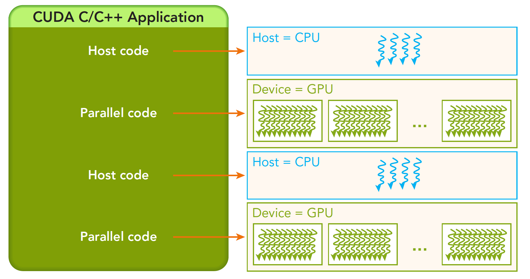
From host serial execution to calling the kernel function (after the kernel function is called, control immediately returns to the host thread -- that is, when the first parallel code executes, the second host code segment has likely already begun executing synchronously).
Our research will proceed in the following hierarchy:
- Memory
- Threads
- Kernel functions
- Launching kernel functions
- Writing kernel functions
- Validating kernel functions
- Error handling
Memory Management
Memory management is very common in traditional serial programs. Memory in register space and stack space is managed by the machine itself, while heap space is controlled by the user for allocation and release. CUDA programs are similar -- CUDA provides APIs for allocating and managing device memory. You can also use CUDA to manage host memory, and traditional standard libraries can also handle host memory management.
The following table compares some standard C functions with CUDA C APIs:
| Standard C Function | CUDA C Function | Description |
|---|---|---|
| malloc | cudaMalloc | Memory allocation |
| memcpy | cudaMemcpy | Memory copy |
| memset | cudaMemset | Memory set |
| free | cudaFree | Free memory |
Let's first study the most critical step, which involves transferring data through the bus:
cudaError_t cudaMemcpy(void * dst, const void * src, size_t count,
                       cudaMemcpyKind kind)
This function performs memory copy operations and can complete the following processes (cudaMemcpyKind kind):
- cudaMemcpyHostToHost
- cudaMemcpyHostToDevice
- cudaMemcpyDeviceToHost
- cudaMemcpyDeviceToDevice
The direction of these four processes is clearly indicated by their names -- I won't elaborate. If the function executes successfully, it returns cudaSuccess; otherwise, it returns cudaErrorMemoryAllocation.
The following function can translate the above error codes into detailed messages:
char* cudaGetErrorString(cudaError_t error)
Memory is hierarchical. The following diagram provides a simple description, though it's not entirely accurate. We'll go into detail about each specific component later:
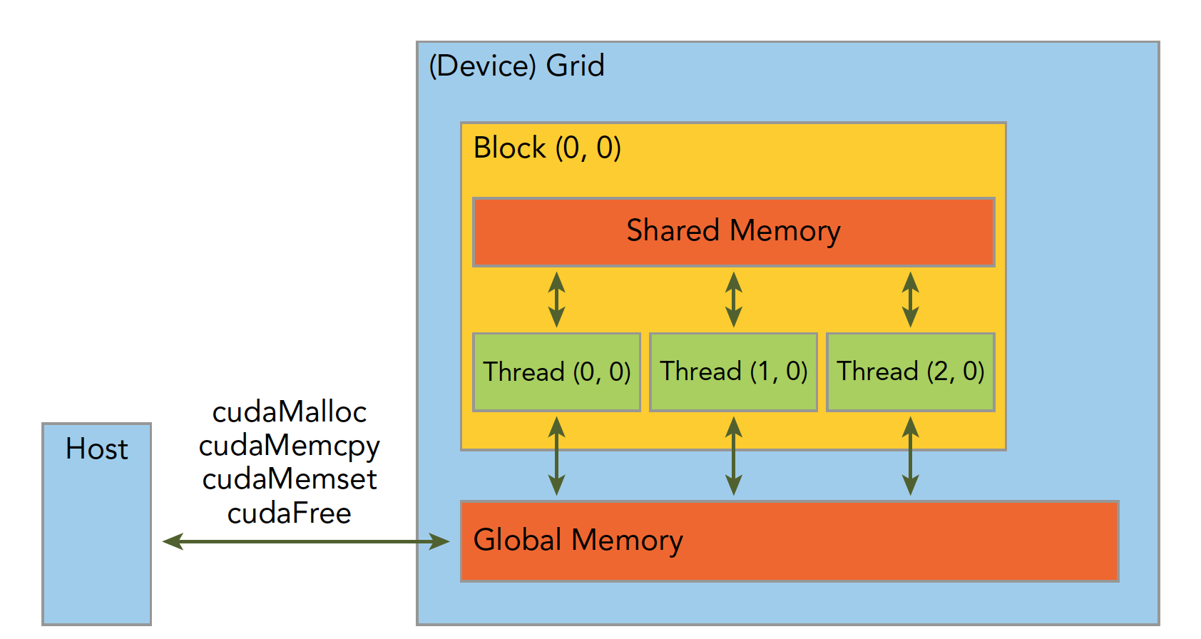
Shared Memory and Global Memory will be studied in great depth later. Here, let's use an example: addition of two vectors.
Code repository: https://github.com/Tony-Tan/CUDA_Freshman
/*
 * https://github.com/Tony-Tan/CUDA_Freshman
 * 3_sum_arrays
 */
#include <cuda_runtime.h>
#include <stdio.h>
#include "freshman.h"

void sumArrays(float * a, float * b, float * res, const int size)
{
    for(int i = 0; i < size; i += 4)
    {
        res[i] = a[i] + b[i];
        res[i+1] = a[i+1] + b[i+1];
        res[i+2] = a[i+2] + b[i+2];
        res[i+3] = a[i+3] + b[i+3];
    }
}

__global__ void sumArraysGPU(float *a, float *b, float *res)
{
    int i = threadIdx.x;
    res[i] = a[i] + b[i];
}

int main(int argc, char **argv)
{
    int dev = 0;
    cudaSetDevice(dev);

    int nElem = 32;
    printf("Vector size:%d\n", nElem);
    int nByte = sizeof(float) * nElem;
    float *a_h = (float*)malloc(nByte);
    float *b_h = (float*)malloc(nByte);
    float *res_h = (float*)malloc(nByte);
    float *res_from_gpu_h = (float*)malloc(nByte);
    memset(res_h, 0, nByte);
    memset(res_from_gpu_h, 0, nByte);

    float *a_d, *b_d, *res_d;
    CHECK(cudaMalloc((float**)&a_d, nByte));
    CHECK(cudaMalloc((float**)&b_d, nByte));
    CHECK(cudaMalloc((float**)&res_d, nByte));

    initialData(a_h, nElem);
    initialData(b_h, nElem);

    CHECK(cudaMemcpy(a_d, a_h, nByte, cudaMemcpyHostToDevice));
    CHECK(cudaMemcpy(b_d, b_h, nByte, cudaMemcpyHostToDevice));

    dim3 block(nElem);
    dim3 grid(nElem / block.x);
    sumArraysGPU<<<grid, block>>>(a_d, b_d, res_d);
    printf("Execution configuration<<<%d,%d>>>\n", block.x, grid.x);

    CHECK(cudaMemcpy(res_from_gpu_h, res_d, nByte, cudaMemcpyDeviceToHost));
    sumArrays(a_h, b_h, res_h, nElem);

    checkResult(res_h, res_from_gpu_h, nElem);
    cudaFree(a_d);
    cudaFree(b_d);
    cudaFree(res_d);

    free(a_h);
    free(b_h);
    free(res_h);
    free(res_from_gpu_h);

    return 0;
}
Then use nvcc to compile our program (our code repository uses cmake to manage the project, which is more convenient).
Let me explain the memory management part of the code:
cudaMalloc((float**)&a_d, nByte);
Allocates memory on the device side. To distinguish between device and host memory, we can add suffixes or prefixes to variables: h_ for host, d_ for device.
A common mistake is mixing up device and host memory addresses!
Thread Management
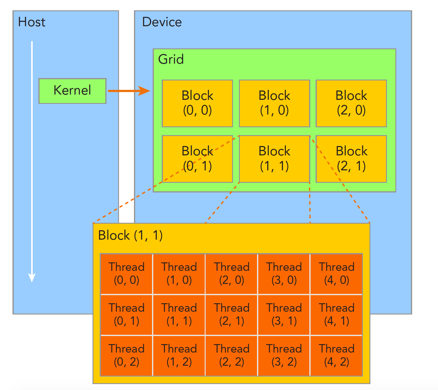
When a kernel function begins executing, how to organize GPU threads becomes the most important issue. We must be clear: a kernel function can only have one grid, a grid can have many blocks, and each block can have many threads. This hierarchical organization makes our parallel processes more flexible:
Threads within a thread block can achieve the following cooperation:
- Synchronization
- Shared memory
Threads in different blocks cannot interfere with each other! They are physically isolated!
Next, we need to give each thread a number. We know each thread executes the same serial code, so how do we make this same code correspond to different data? The first step is to distinguish threads from each other so they can correspond to their respective threads, allowing threads to distinguish their own data. If threads have no identifying marks, there's no way to determine their behavior.
Thread indices are determined by the following two built-in structures:
- blockIdx (the position index of a thread block within the thread grid)
- threadIdx (the position index of a thread within a thread block)
Note that "Idx" is an abbreviation for "index." These two built-in structures are based on the uint3 definition, containing a structure of three unsigned integers, specified through three fields:
- blockIdx.x
- blockIdx.y
- blockIdx.z
- threadIdx.x
- threadIdx.y
- threadIdx.z
The above are coordinates. Of course, we also need two corresponding structures to store their ranges -- the ranges of the three fields in blockIdx and the three fields in threadIdx:
- blockDim
- gridDim
They are variables of type dim3 (a data structure based on uint3), also containing three fields: x, y, z:
- blockDim.x
- blockDim.y
- blockDim.z
Grid and block dimensions are generally two-dimensional or three-dimensional. That is, a grid is usually divided into two-dimensional blocks, and each block is commonly divided into three-dimensional threads.
Note: dim3 is manually defined and visible on the host side. uint3 is visible during device-side execution and cannot be modified while the kernel is running. Once initialization is complete, the uint3 value doesn't change. They are different! This must be noted.
Here is a piece of code that checks block indices and dimensions:
/*
 * 1_check_dimension
 */
#include <cuda_runtime.h>
#include <stdio.h>

__global__ void checkIndex(void)
{
    printf("threadIdx:(%d,%d,%d) blockIdx:(%d,%d,%d) blockDim:(%d,%d,%d) "
           "gridDim:(%d,%d,%d)\n", threadIdx.x, threadIdx.y, threadIdx.z,
           blockIdx.x, blockIdx.y, blockIdx.z, blockDim.x, blockDim.y, blockDim.z,
           gridDim.x, gridDim.y, gridDim.z);
}

int main(int argc, char **argv)
{
    int nElem = 6;
    dim3 block(3);
    dim3 grid((nElem + block.x - 1) / block.x);
    printf("grid.x %d grid.y %d grid.z %d\n", grid.x, grid.y, grid.z);
    printf("block.x %d block.y %d block.z %d\n", block.x, block.y, block.z);
    checkIndex<<<grid, block>>>();
    cudaDeviceReset();
    return 0;
}
You can run this to see results for different thread decomposition methods.
The following code checks grid and block sizes:
/*
 * 2_grid_block
 */
#include <cuda_runtime.h>
#include <stdio.h>

int main(int argc, char **argv)
{
    int nElem = 1024;
    dim3 block(1024);
    dim3 grid((nElem - 1) / block.x + 1);
    printf("grid.x %d block.x %d\n", grid.x, block.x);

    block.x = 512;
    grid.x = (nElem - 1) / block.x + 1;
    printf("grid.x %d block.x %d\n", grid.x, block.x);

    block.x = 256;
    grid.x = (nElem - 1) / block.x + 1;
    printf("grid.x %d block.x %d\n", grid.x, block.x);

    block.x = 128;
    grid.x = (nElem - 1) / block.x + 1;
    printf("grid.x %d block.x %d\n", grid.x, block.x);

    cudaDeviceReset();
    return 0;
}
Grid and block dimensions have several limiting factors. Block size is primarily related to available computational resources, such as registers and shared memory.
The method of dividing into grids and blocks allows our CUDA program to execute on any device.
Summary
Today we covered the first part, mainly giving a macro-level view of how memory, threads, and kernel functions interact. Through the interplay of these features, CUDA programs can execute correctly at high speed. The next article will provide an overview of some kernel function characteristics.