University Physics I
Mechanics
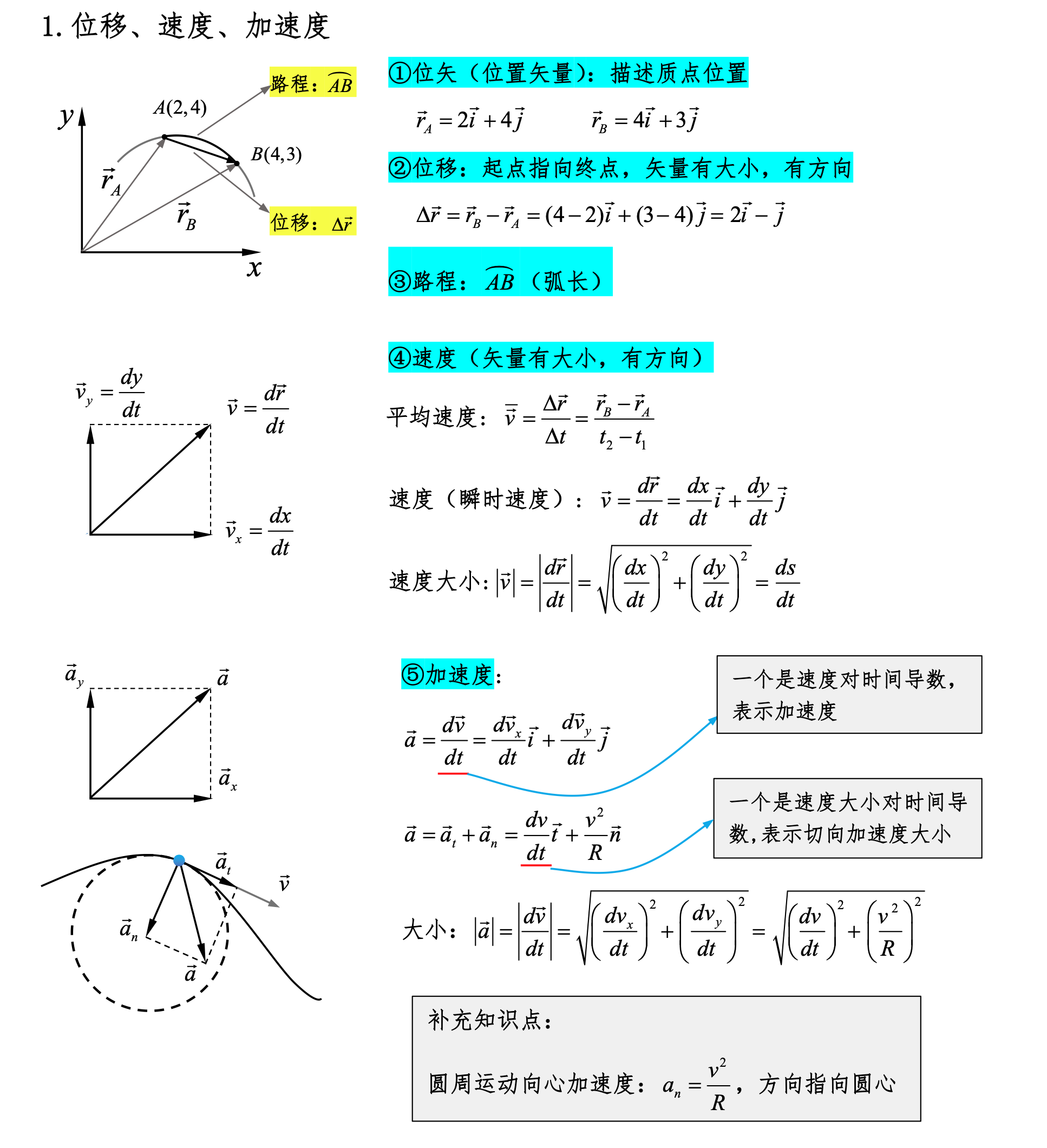
Displacement, Velocity, Acceleration
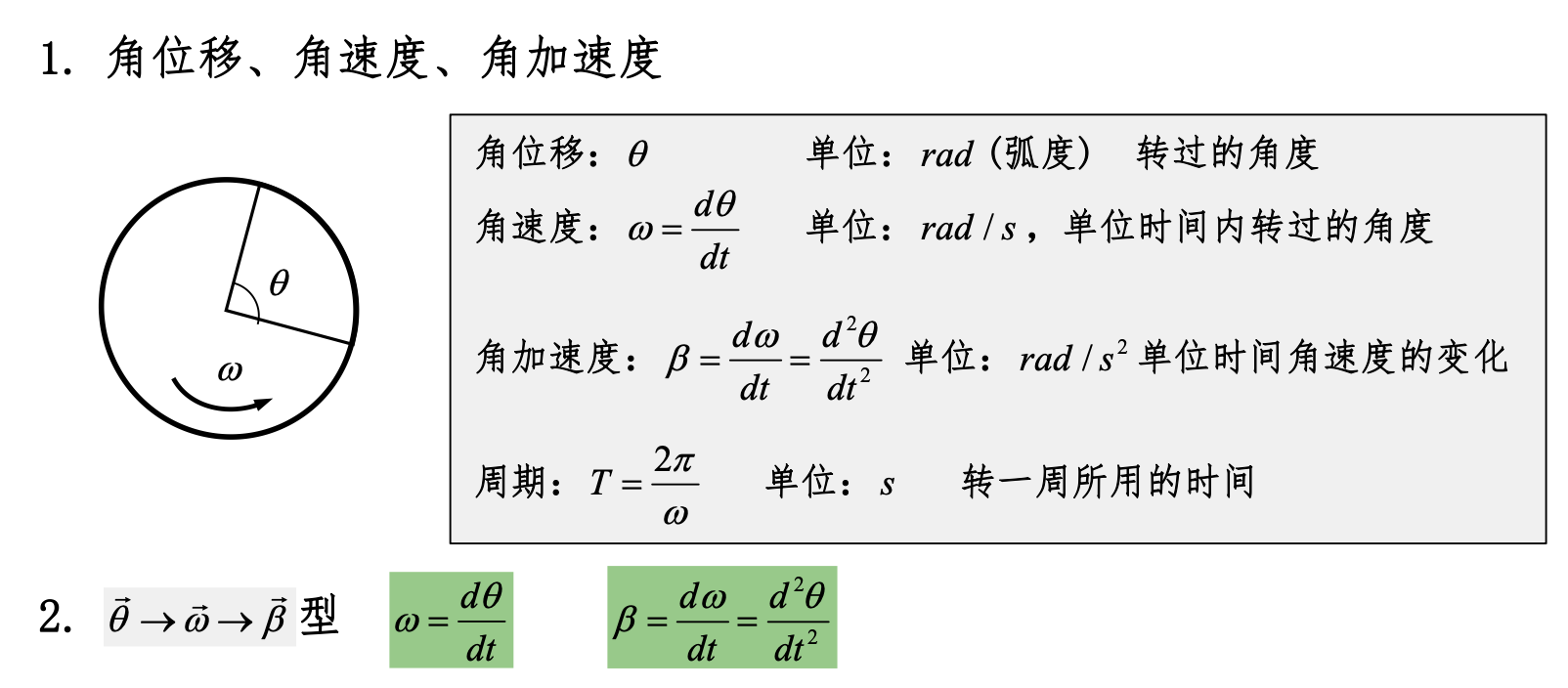
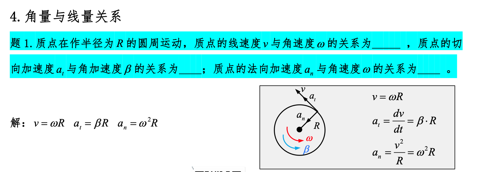
Angular Displacement, Angular Velocity, Angular Acceleration
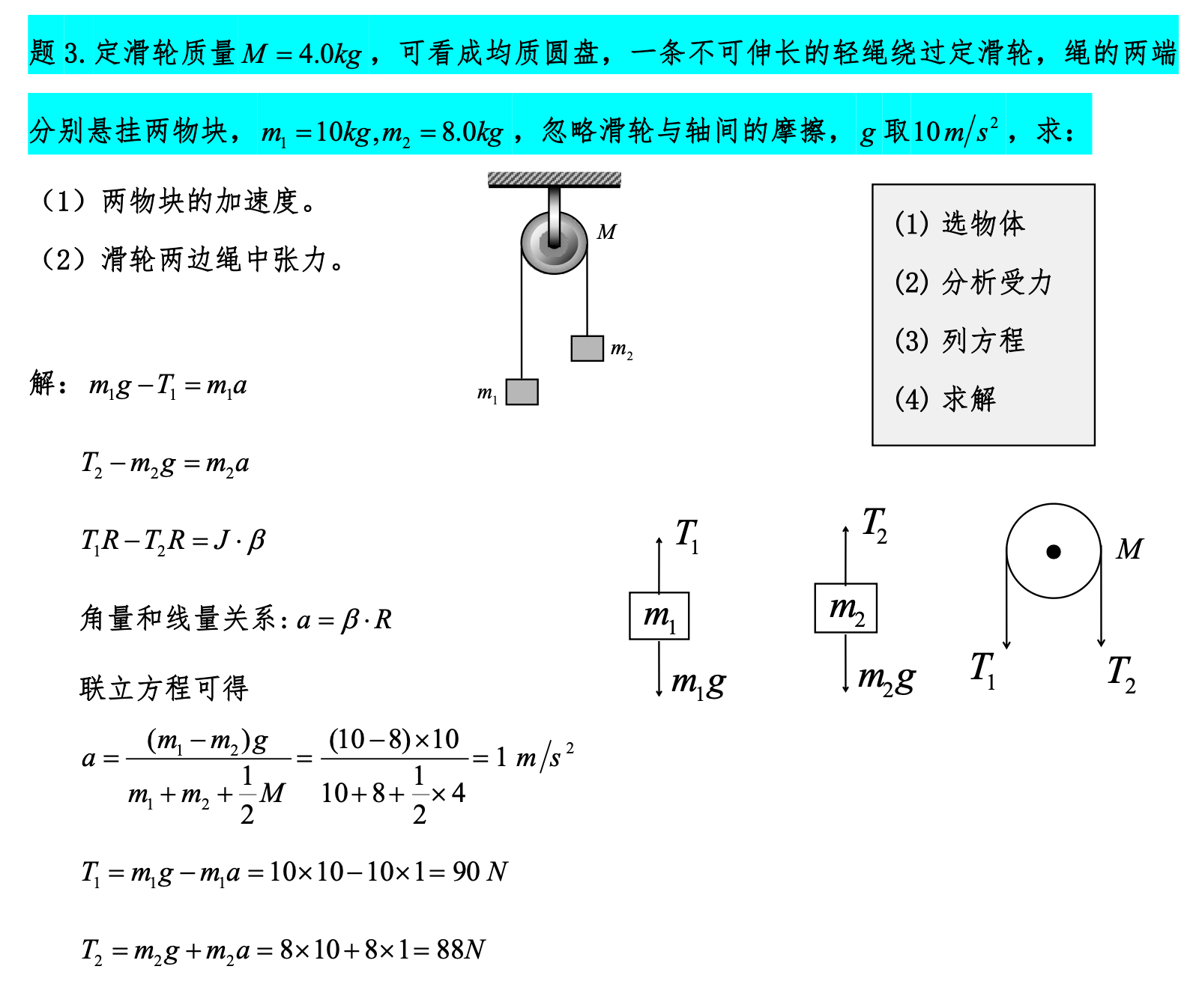
Pulley-Block Model
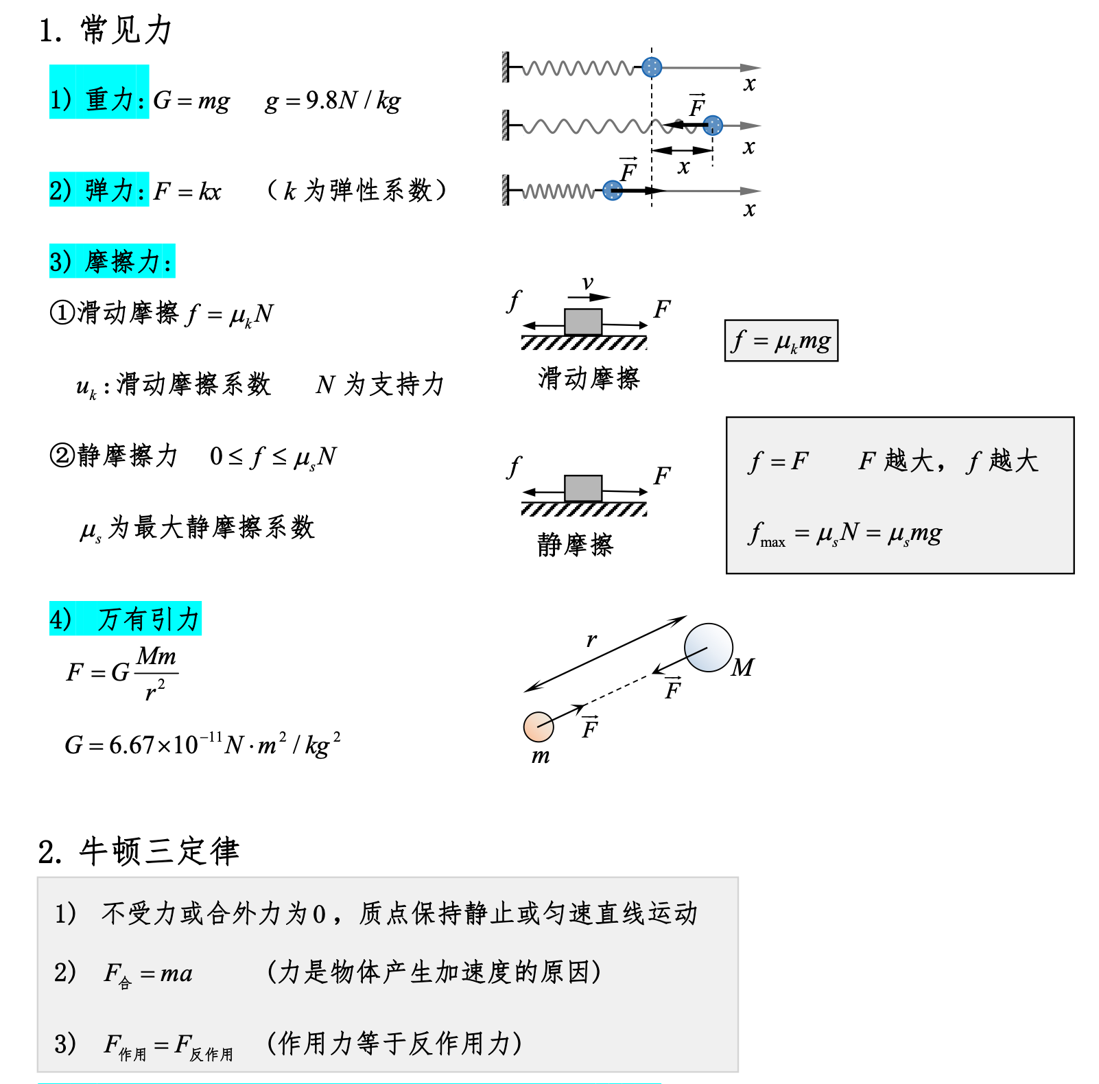
Newton's Third Law
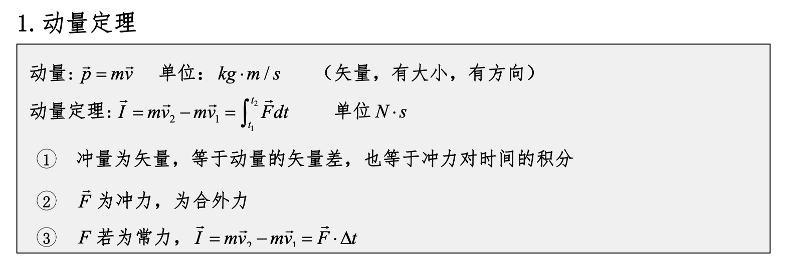
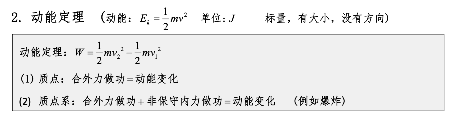
Impulse-Momentum Theorem, Work-Energy Theorem
Conservative Forces, Potential Energy
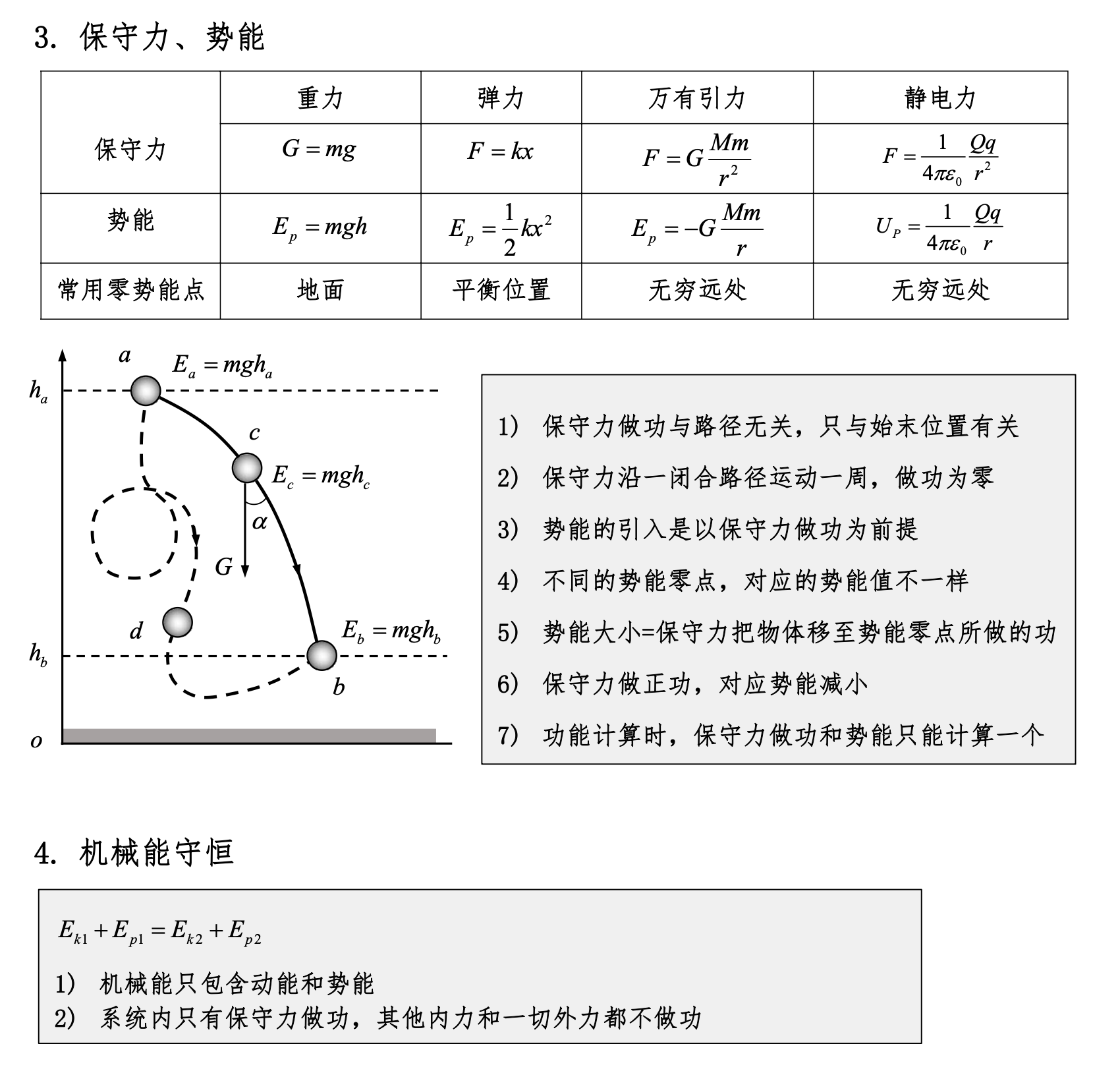
Conditions for Conservation of Mechanical Energy
Only conservative forces do work within the system
Conservation of mechanical energy means that the total mechanical energy of a system (the sum of kinetic and potential energy) remains constant under certain conditions. The specific conditions are:
- Only conservative forces do work within the system: Conservative forces are those whose work depends only on the initial and final positions, not on the path, such as gravity and spring forces. If only conservative forces do work within the system, mechanical energy is conserved.
- No non-conservative forces (such as friction, air resistance, etc.) do work: Non-conservative forces doing work causes energy to dissipate as heat or other forms, making mechanical energy no longer conserved.
- The system is closed: The system does not exchange energy with the outside world.
Note that for systems where friction does work, mechanical energy is not conserved.
Conditions for Conservation of Momentum
The system is not subject to external forces (or the net external force is zero)
Conservation of momentum means that the total momentum of a system remains constant under certain conditions. The specific conditions are:
- The net force of external and internal forces on the system is zero: If the system is not subject to external forces (or the net external force is zero), the total momentum of the system is conserved.
- The system is closed: The system does not exchange momentum with the outside world.
- Internal forces obey Newton's Third Law: The interaction and reaction forces between parts of the system are equal in magnitude and opposite in direction.
In summary:
- Conservation of mechanical energy: Only conservative forces do work within the system, and no energy is lost in other forms.
- Conservation of momentum: The system is not subject to external forces (or the net external force is zero), and the system is closed.
These two laws have wide applications in physics and apply to different physical processes and systems.
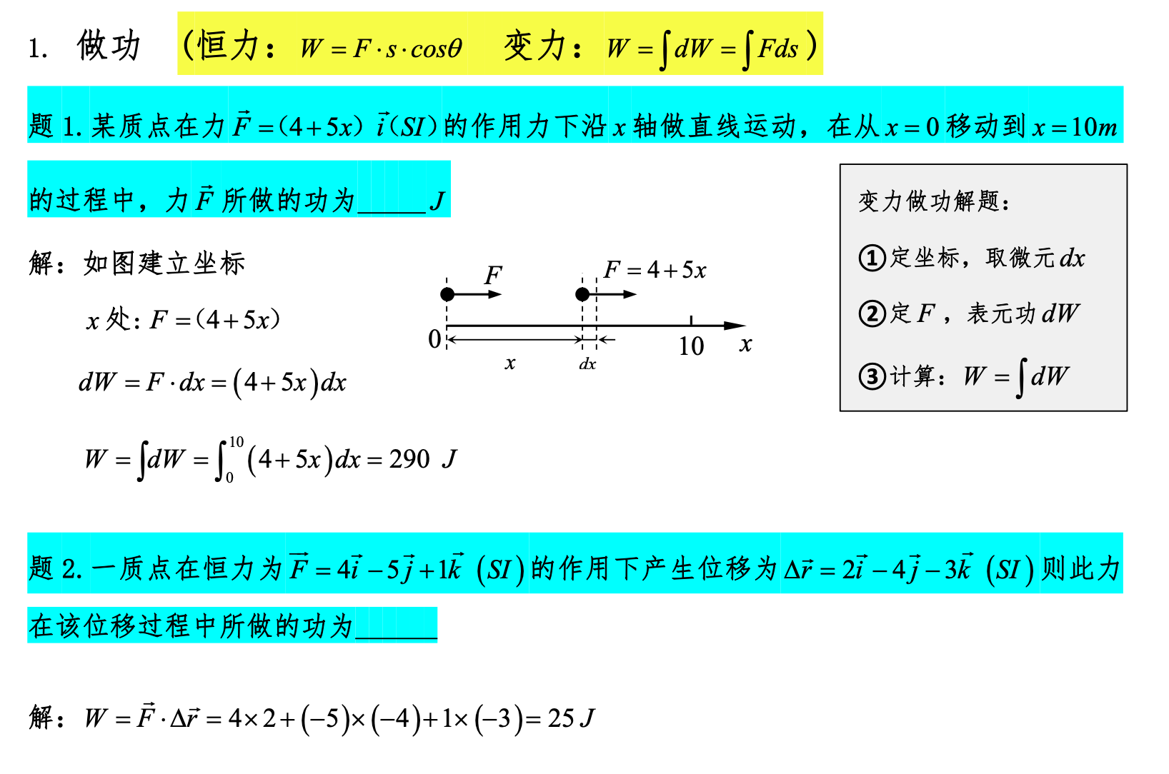
Work Done by Variable Forces
Use integration for work done by variable forces.
Note that if the force has components in multiple dimensions, calculate the product of force and displacement for each dimension separately and then sum them.
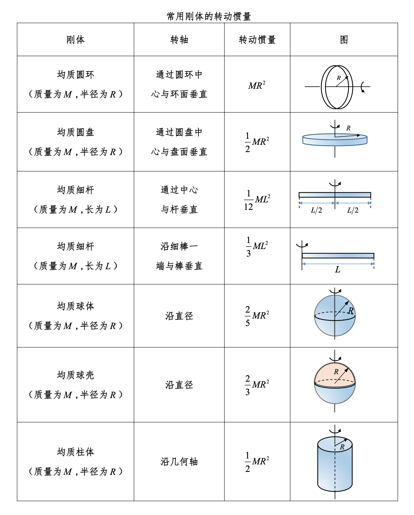
Moment of Inertia

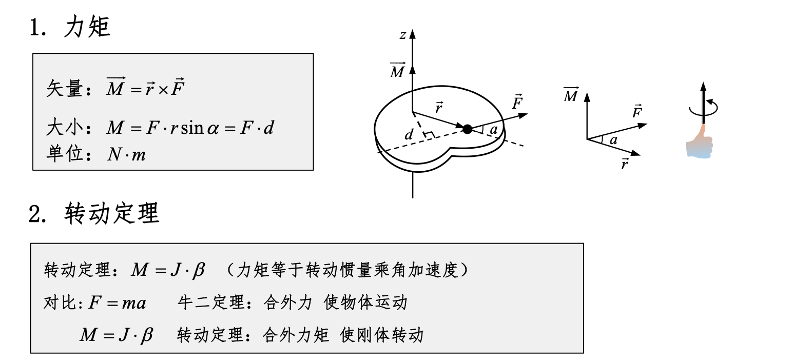
Torque
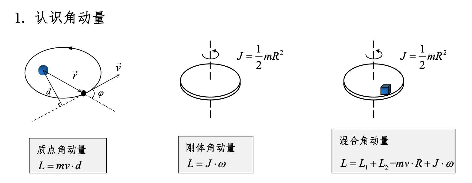
Angular Momentum
Conditions for Conservation of Angular Momentum
-
The system is not subject to external torque (net external torque equals 0): If the system is not subject to external torque (or the net external torque is zero), the total angular momentum of the system is conserved. External torque refers to the torque of external forces acting on the system relative to a fixed point or axis.
-
The system is closed: The system does not exchange angular momentum with the outside world, meaning no external object applies torque to the system.
-
The net internal torque is zero: The torques within the system cancel each other out. According to Newton's Third Law, the action and reaction torques between internal forces are equal and opposite, so their net effect is zero.
-
Applications of conservation of angular momentum:
-
Celestial motion: For example, the orbital motion of a planet around a star. If the influence of other celestial bodies is ignored, the planet's angular momentum is conserved.
-
Rotating objects: For example, a figure skater adjusts their rotation speed by changing the position of their arms and legs during spinning, because their angular momentum is conserved.
-
Particle physics: In particle collisions and decay processes, conservation of angular momentum is an important constraint.
Work and Energy of Rigid Body Rotation
Work Done by Torque
Torque is the rotational effect of a force causing an object to rotate. For a rigid body, torque is defined as the product of the force magnitude and the moment arm (the perpendicular distance from the point of force application to the axis of rotation). Mathematically, torque τ can be expressed as: where r is the moment arm and F is the force magnitude.
When torque acts on a rigid body and causes it to rotate, the torque does work. The expression for work done by torque is: where W is the work, τ is the constant torque, and θ is the angle of rotation (in radians).
Kinetic Energy Theorem for Rigid Body Rotation
The rotational kinetic energy of a rigid body is the kinetic energy due to its rotation about a fixed axis. The rotational kinetic energy K_rot can be expressed as: where I is the moment of inertia of the rigid body about the axis of rotation, and ω is the angular velocity.
The kinetic energy theorem states that the total work done by external torques on a rigid body equals the change in the rigid body's kinetic energy. For a rotating rigid body, the kinetic energy theorem can be expressed as: where ΔK_rot is the change in rotational kinetic energy and W_net is the work done by the net torque.
Conservation of Mechanical Energy for Rigid Bodies
When no non-conservative forces (such as friction) act, the mechanical energy of a rigid body is conserved. Mechanical energy includes kinetic energy and potential energy. For rigid body rotation, the law of conservation of mechanical energy can be expressed as: where:
- K_trans is the translational kinetic energy of the rigid body,
- K_rot is the rotational kinetic energy of the rigid body,
- U is the potential energy of the rigid body.
For pure rotation, the translational kinetic energy is zero. Therefore, the law of conservation of mechanical energy simplifies to:
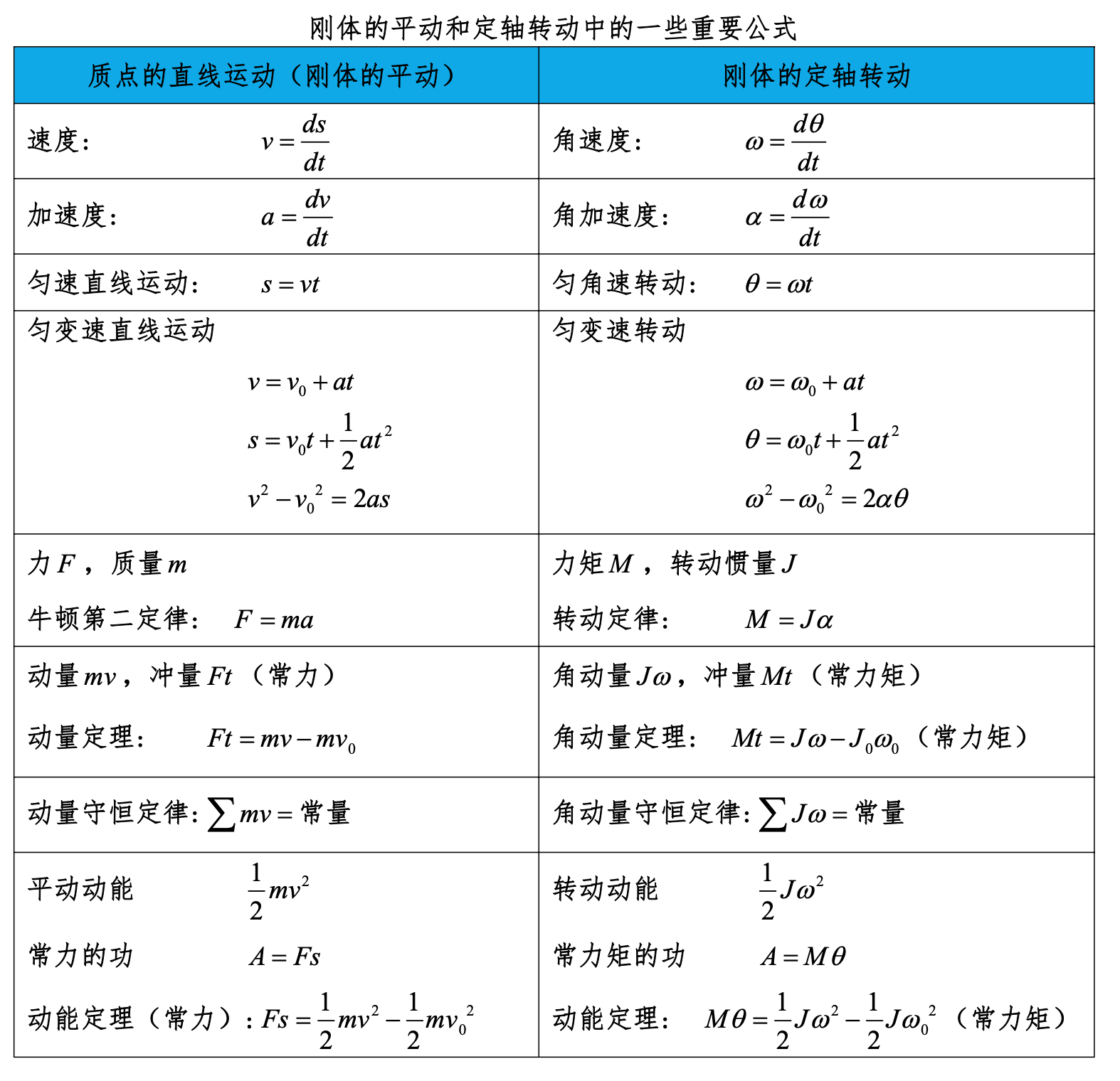
Important Formulas for Rigid Body Translation and Rotation
Oscillations and Waves
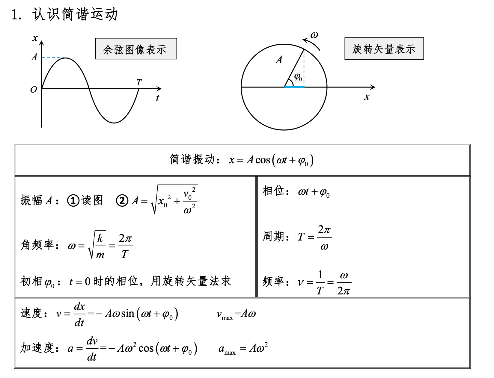
Simple Harmonic Motion
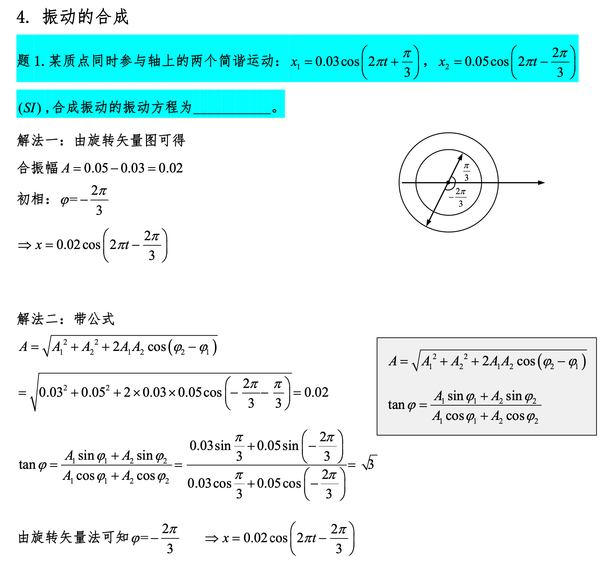
Superposition of Oscillations
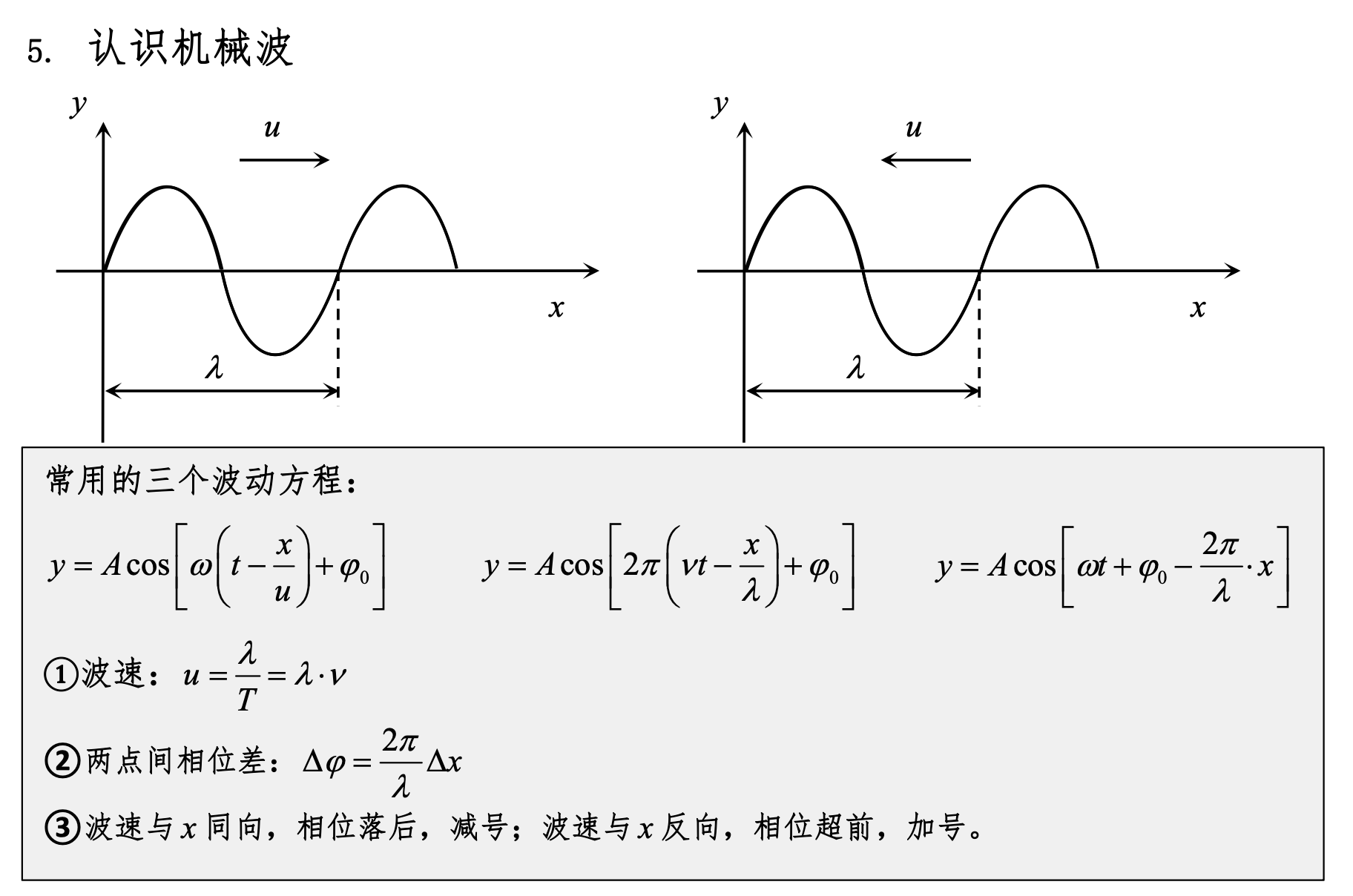
Mechanical Waves, Wave Equation
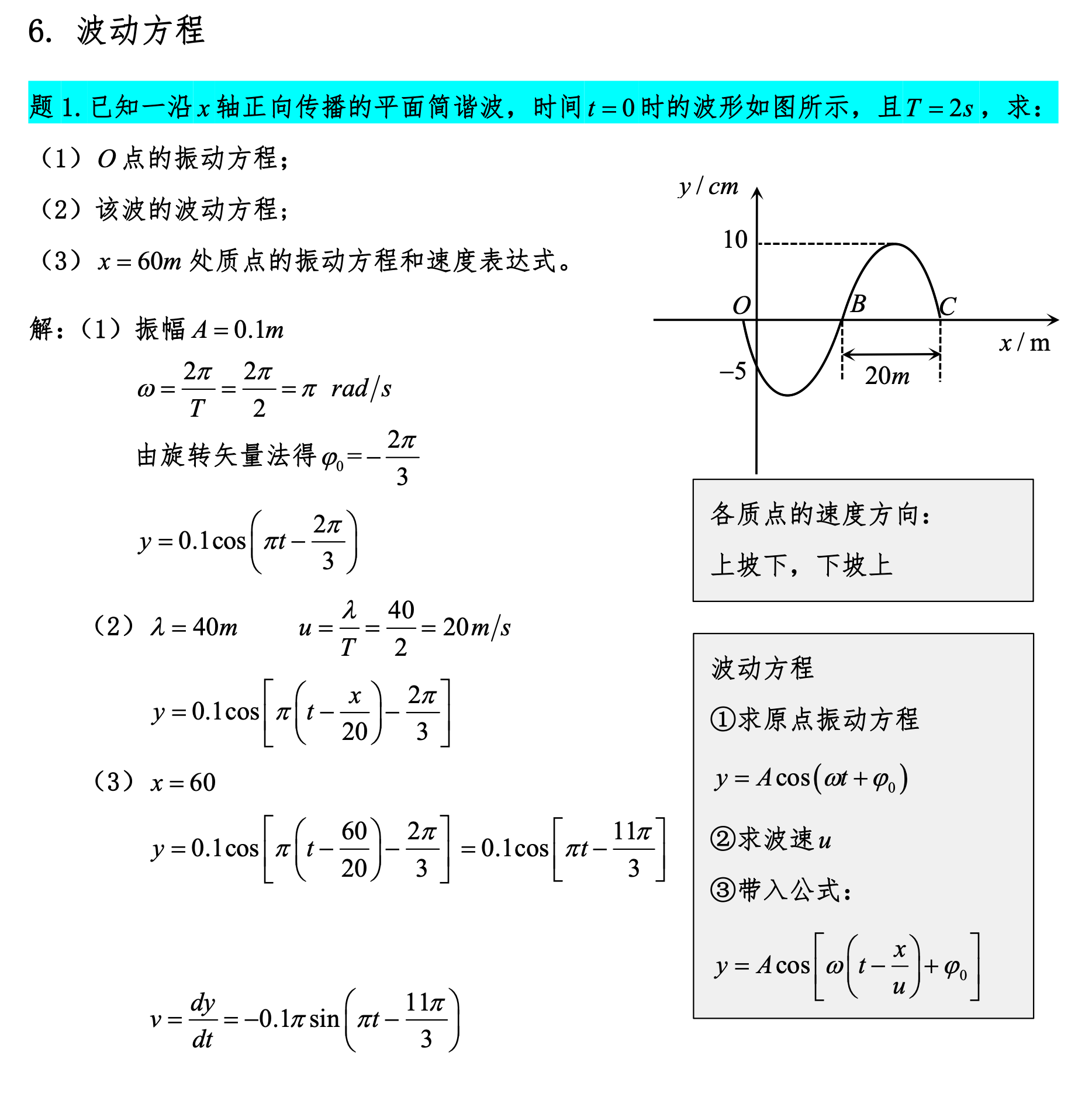
The wave section of university physics involves the study of wave phenomena and energy transfer. Here are some key points about wave energy:
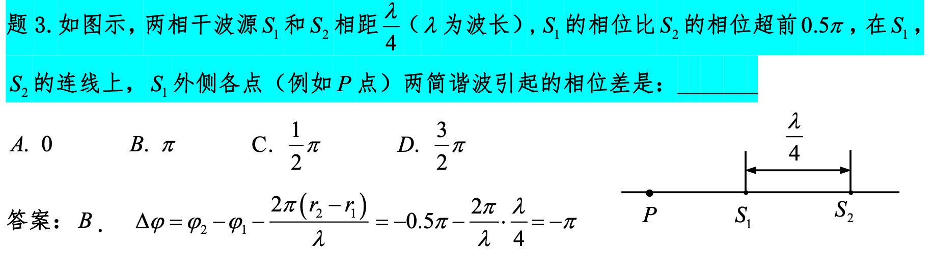
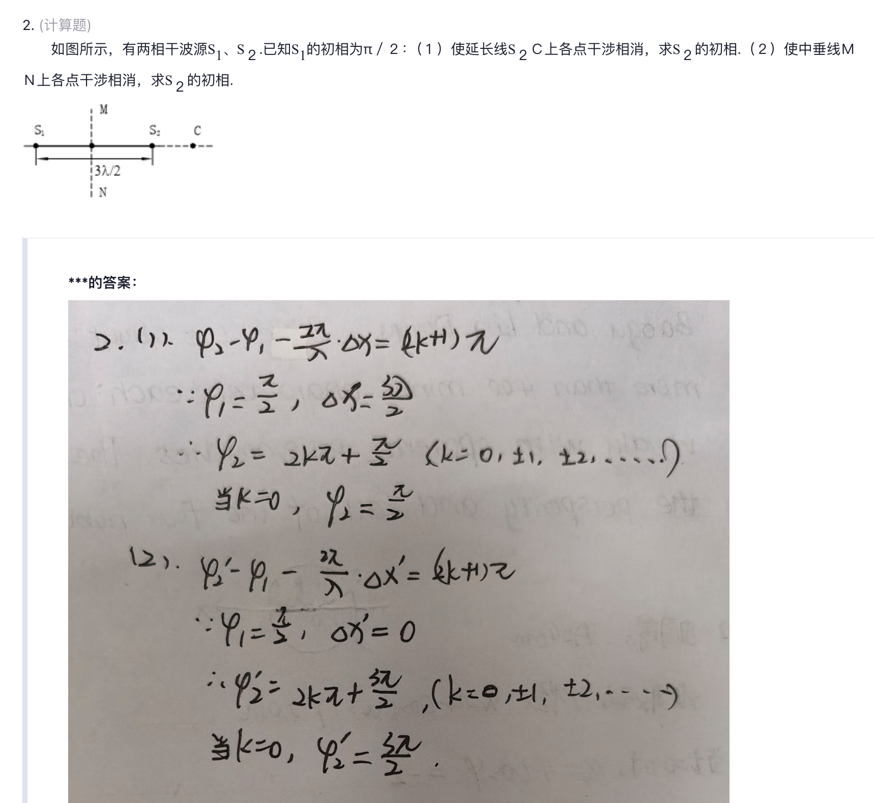
Wave Interference
Note the phase difference formula for two waves at a certain point in the answer.
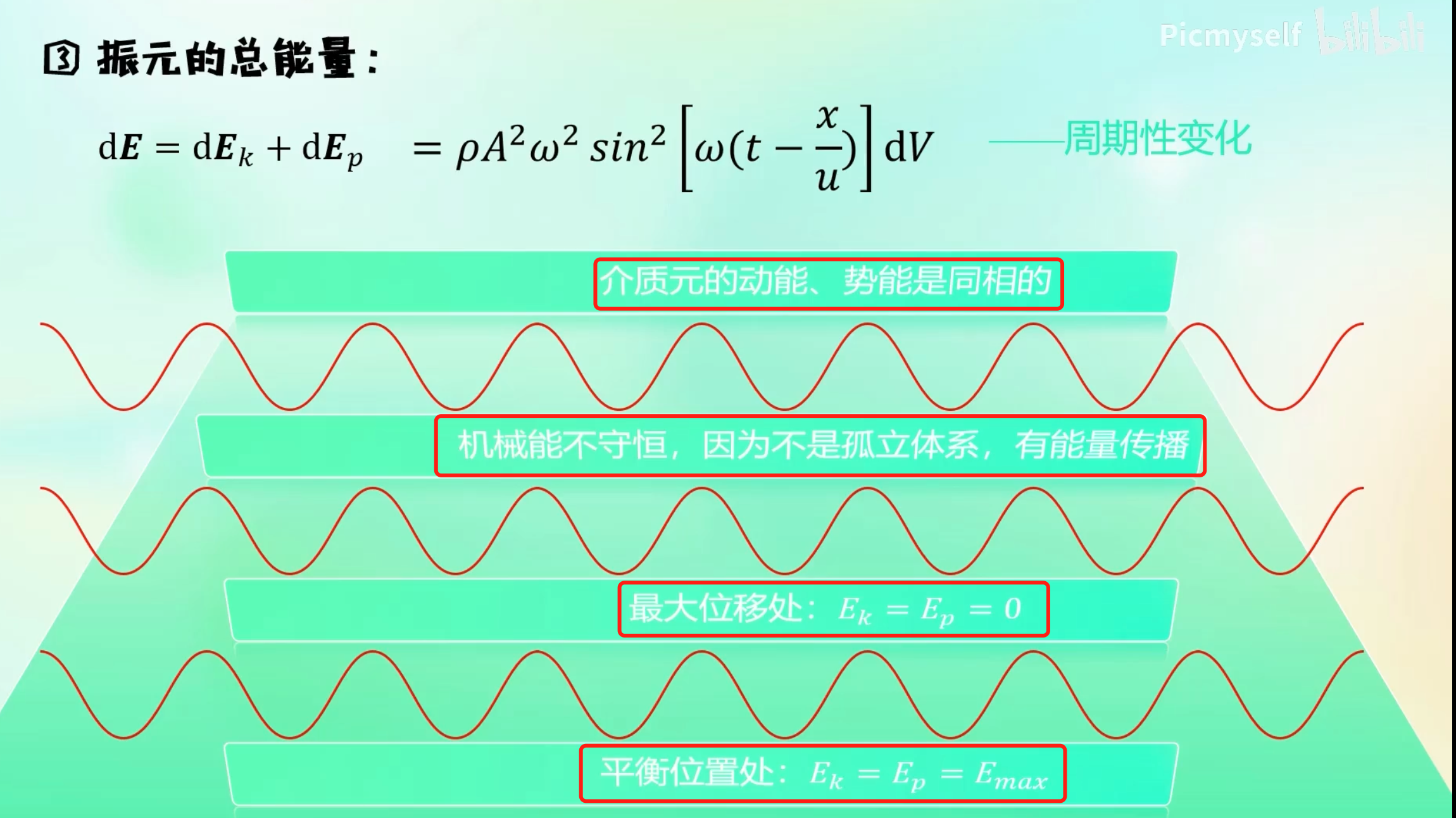
Wave Energy
Note that this should be distinguished from single-particle oscillation.
-
Energy propagation: Waves transfer energy, not matter itself.
-
Wave energy: Can be divided into kinetic energy and potential energy. Kinetic energy comes from the motion of the medium, and potential energy comes from the deformation of the medium (such as compression or stretching).
-
Amplitude and energy: The energy of a wave is proportional to the square of the amplitude. That is, the greater the amplitude, the more energy the wave carries.
Four conclusions about wave volume element energy: Note that this refers to waves.
- The kinetic energy and potential energy of the volume element are equal.
- The mechanical energy of the volume element is not conserved because it is not an independent system — waves transfer energy.
- At maximum displacement: both kinetic energy and potential energy are zero.
- At equilibrium position: both kinetic energy and potential energy are maximum.
For detailed explanation, see the video Energy of Mechanical Waves
Optics
Double-Slit Interference
Equal Inclination Interference, Half-Wave Loss
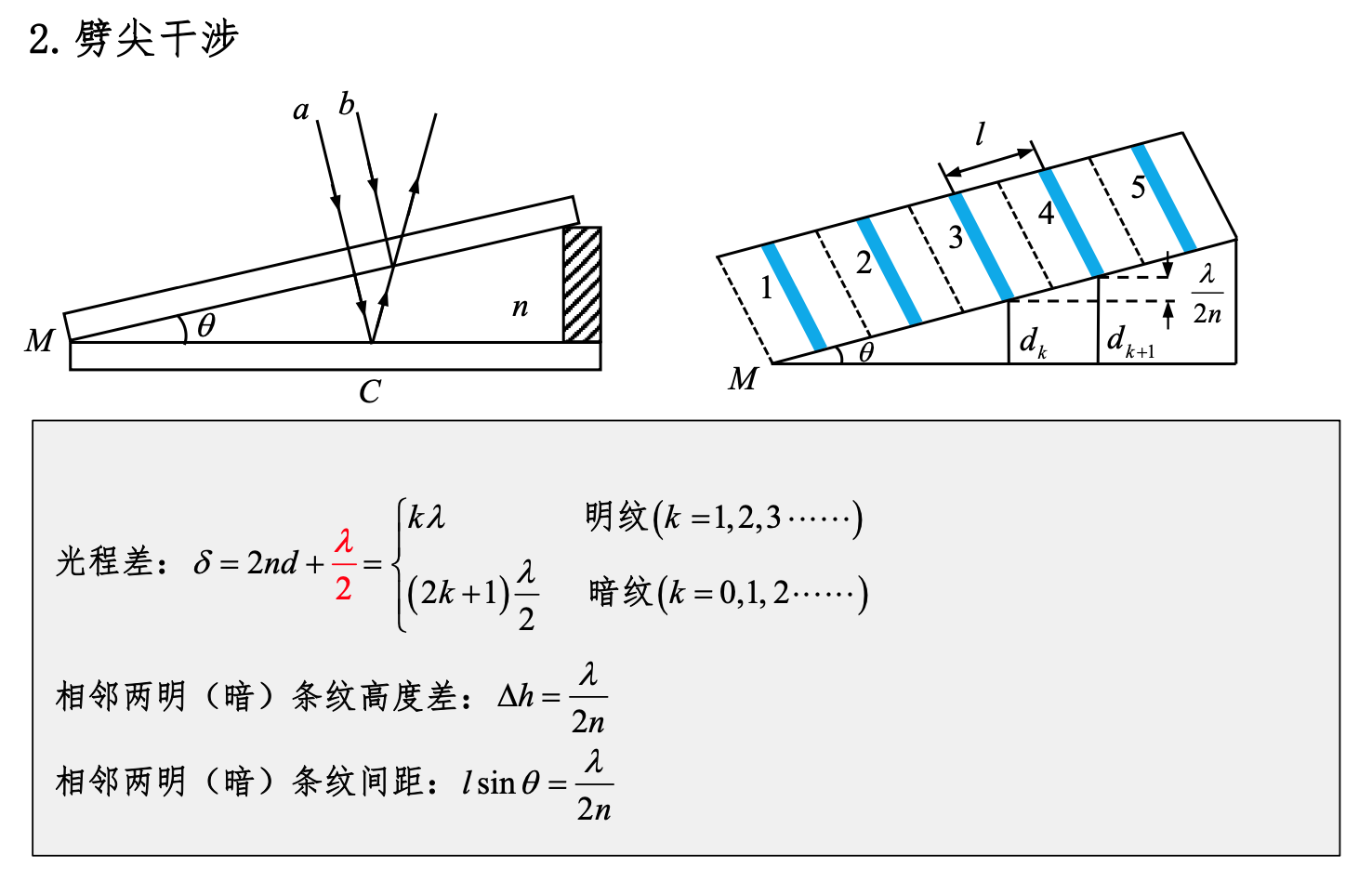
Wedge Interference
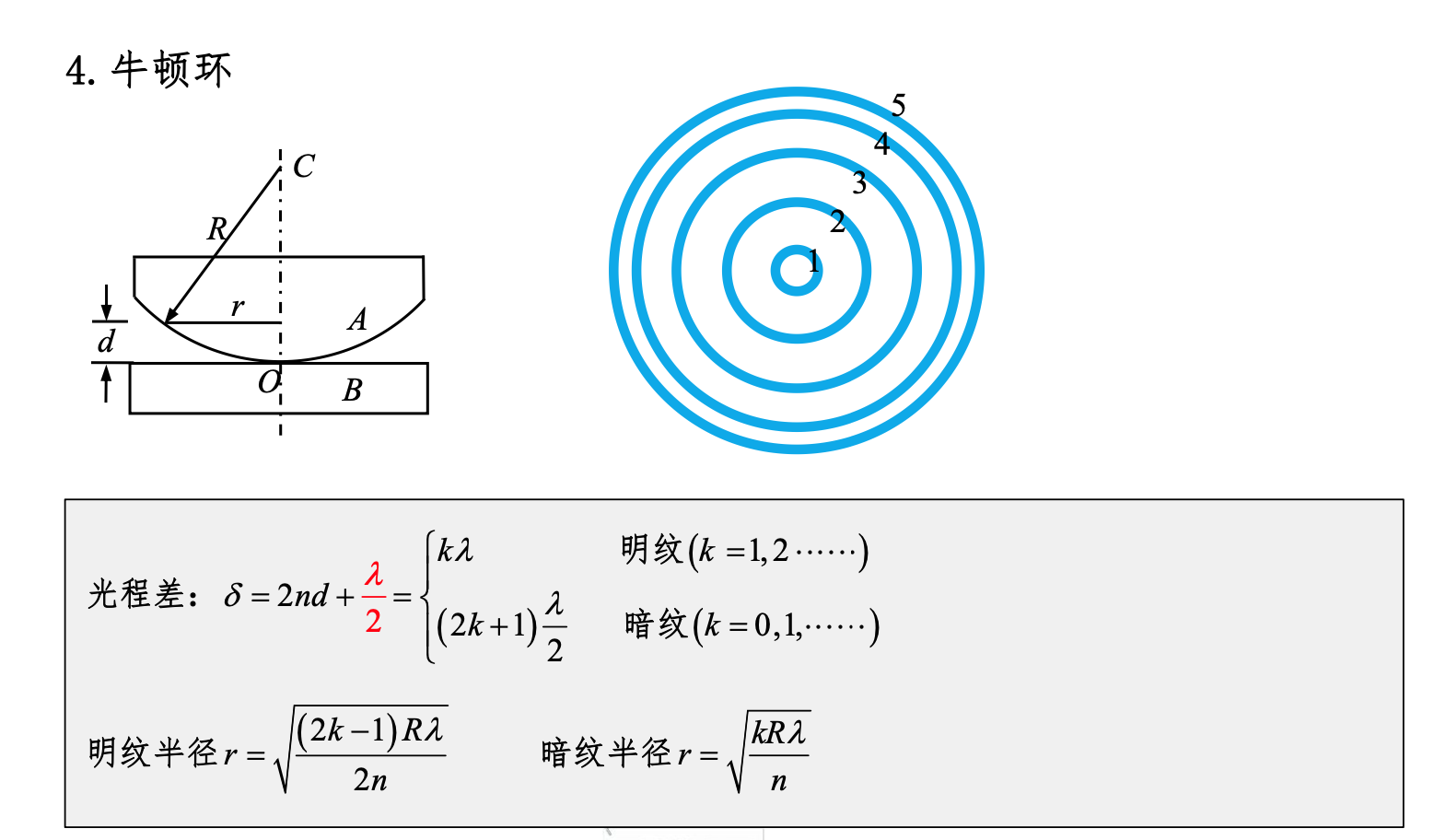
Newton's Rings
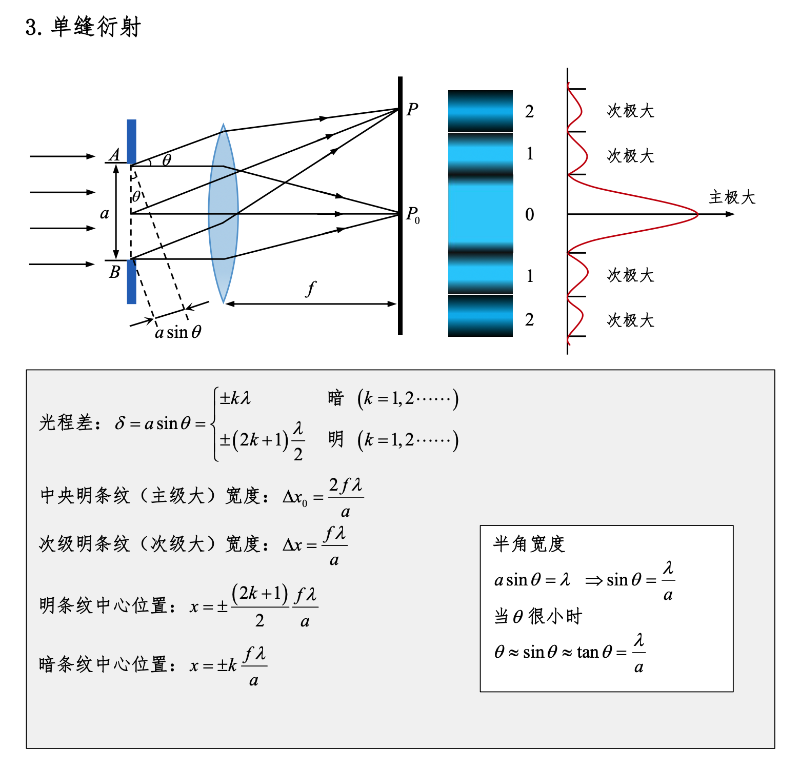
Single-Slit Diffraction
Diffraction Grating
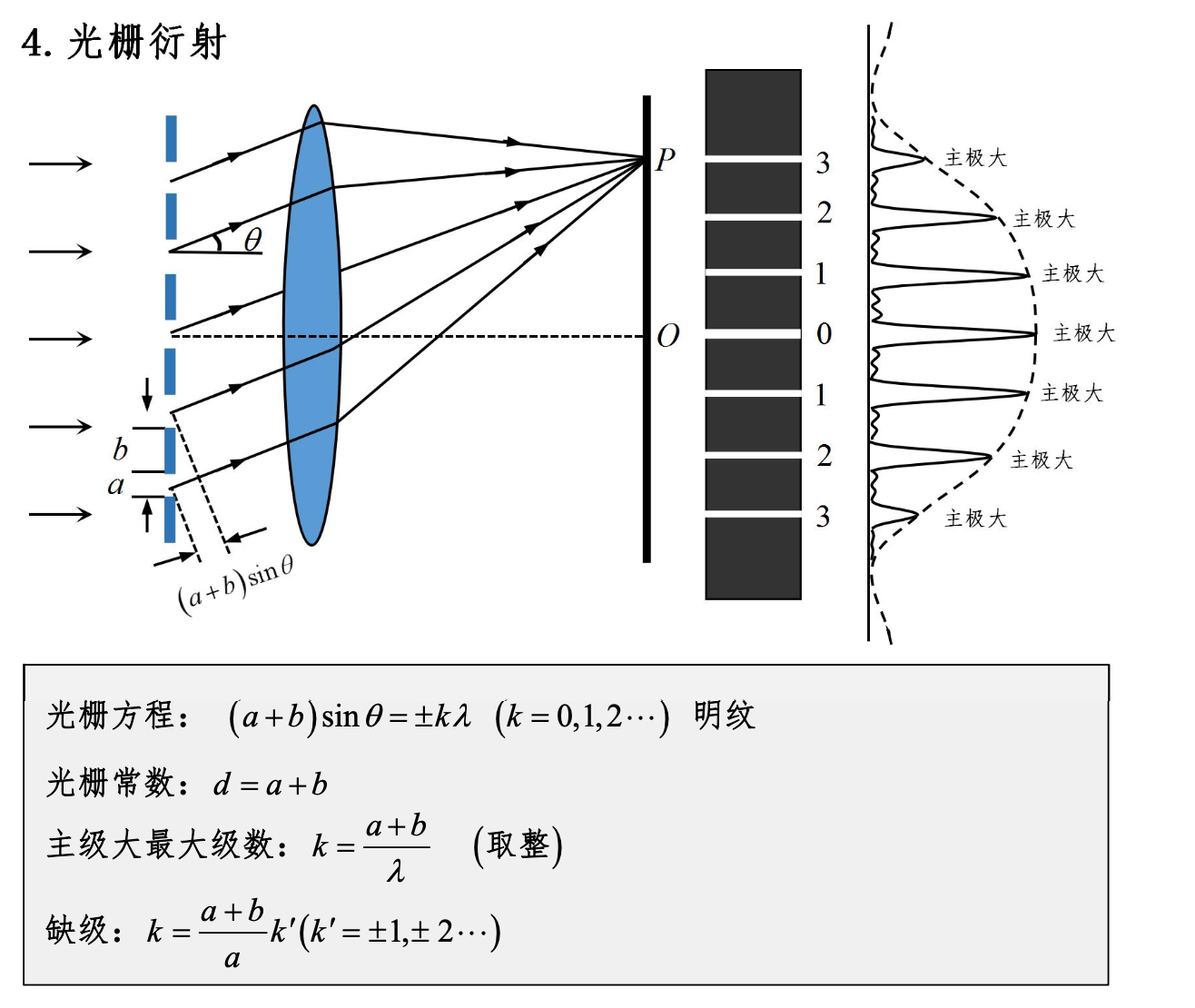
The unit of the grating constant is a length unit, typically expressed in meters (m), millimeters (mm), micrometers (µm), or nanometers (nm).
Grating Constant
The grating constant is defined as the distance between two adjacent slits or rulings on a grating, also known as the grating period.
Common Units
- Meters (m): Used for very large grating periods.
- Millimeters (mm): Commonly used for general gratings.
- Micrometers (µm): Very common because grating periods are usually in this range.
- Nanometers (nm): Used for very fine gratings.
Examples
- For a common grating with 1000 lines per millimeter, the grating constant is 1 micrometer (µm).
- For a finer grating with 10,000 lines per millimeter, the grating constant is 100 nanometers (nm).
Summary
The grating constant is typically expressed in meters (m), millimeters (mm), micrometers (µm), or nanometers (nm). The choice of unit depends on the specific size and application of the grating.
Length Unit Conversion
-
Meters (m)
- 1 m = 100 cm
- 1 m = 1,000 mm
- 1 m = 10⁹ nm
- 1 m = 10⁶ µm
- 1 m = 10¹² pm
- 1 m = 10¹⁰ Å
-
Centimeters (cm)
- 1 cm = 0.01 m
- 1 cm = 10 mm
- 1 cm = 10⁷ nm
- 1 cm = 10⁴ µm
- 1 cm = 10¹⁰ pm
- 1 cm = 10⁸ Å
-
Millimeters (mm)
- 1 mm = 0.1 cm
- 1 mm = 10⁻³ m
- 1 mm = 10⁶ nm
- 1 mm = 10³ µm
- 1 mm = 10⁹ pm
- 1 mm = 10⁷ Å
-
Micrometers (µm)
- 1 µm = 10⁻⁶ m
- 1 µm = 10⁻⁴ cm
- 1 µm = 1,000 nm
- 1 µm = 10⁶ pm
- 1 µm = 10⁴ Å
-
Nanometers (nm)
- 1 nm = 10⁻⁹ m
- 1 nm = 10⁻⁷ cm
- 1 nm = 10⁻³ µm
- 1 nm = 1,000 pm
- 1 nm = 10 Å
-
Angstroms (Å)
- 1 Å = 10⁻¹⁰ m
- 1 Å = 10⁻⁸ cm
- 1 Å = 10⁻⁴ µm
- 1 Å = 0.1 nm
- 1 Å = 100 pm
-
Picometers (pm)
- 1 pm = 10⁻¹² m
- 1 pm = 10⁻¹⁰ cm
- 1 pm = 10⁻⁶ µm
- 1 pm = 10⁻³ nm
- 1 pm = 0.01 Å
- 1 m = 100 cm = 1,000 mm = 10⁶ µm = 10⁹ nm = 10¹⁰ Å = 10¹² pm
- 1 cm = 0.01 m = 10 mm = 10⁴ µm = 10⁷ nm = 10⁸ Å = 10¹⁰ pm
- 1 mm = 0.1 cm = 0.001 m = 10³ µm = 10⁶ nm = 10⁷ Å = 10⁹ pm
- 1 µm = 10⁻⁶ m = 10⁻⁴ cm = 10⁻³ mm = 10³ nm = 10⁴ Å = 10⁶ pm
- 1 nm = 10⁻⁹ m = 10⁻⁷ cm = 10⁻⁶ mm = 10⁻³ µm = 10 Å = 1,000 pm
- 1 Å = 10⁻¹⁰ m = 10⁻⁸ cm = 10⁻⁷ mm = 10⁻⁴ µm = 0.1 nm = 100 pm
- 1 pm = 10⁻¹² m = 10⁻¹⁰ cm = 10⁻⁹ mm = 10⁻⁶ µm = 10⁻³ nm = 0.01 Å
Week 6 Short Answer Questions
Week 7 Short Answer Questions
- Relationship Between Mechanical Waves and Mechanical Vibration
Mechanical vibration refers to the reciprocating motion of an object or particle near its equilibrium position. Mechanical waves are the propagation of mechanical vibration through a medium. Specifically, when a particle vibrates in a medium, it transmits the vibration to adjacent particles through interactions, forming a wave. This propagation process is a mechanical wave. Therefore, mechanical waves can be regarded as the transmission of mechanical vibration through a medium.
- Conditions for Mechanical Wave Formation
The formation of mechanical waves requires the following conditions:
- Medium: Mechanical waves need a medium to propagate, which can be a solid, liquid, or gas.
- Vibration source: A vibration source is needed to produce the initial mechanical vibration.
- Elasticity and inertia of the medium: The medium must have elasticity (particles in the medium can interact) and inertia (particles have mass).
- Classification of Waves
Waves can be classified according to different criteria:
- By the relationship between propagation direction and particle vibration direction:
- Longitudinal waves: The vibration direction of particles is parallel to the propagation direction of the wave (e.g., sound waves).
- Transverse waves: The vibration direction of particles is perpendicular to the propagation direction of the wave (e.g., water waves, light waves).
- By propagation medium:
- Mechanical waves: Require a medium to propagate (e.g., sound waves, water waves).
- Electromagnetic waves: Can propagate without a medium (e.g., light waves, radio waves).
- By wave shape:
- Plane waves: The wavefront is a plane.
- Spherical waves: The wavefront is a sphere.
- By wave nature:
- Simple harmonic waves: The waveform is a sine or cosine function.
- Non-simple harmonic waves: The waveform is a complex non-sinusoidal function.
- Physical Quantities Describing Waves
The main physical quantities describing waves are:
- Wavelength (λ): The distance between two adjacent wave crests or troughs.
- Frequency (f): The number of wave cycles passing a point per unit time.
- Period (T): The time required to complete one full vibration.
- Wave speed (v): The speed at which the wave propagates through the medium.
- Amplitude (A): The maximum displacement of the wave.
- Phase (φ): Describes the state of the wave at a certain time and position.
- Energy Characteristics of Waves
Wave energy has the following characteristics:
- Energy propagation: Wave energy is transferred along the direction of wave propagation.
- Relationship between energy and amplitude: The energy of a wave is proportional to the square of the amplitude.
- Energy density: The wave energy per unit volume.
- Energy flux density: The energy passing through a unit area per unit time, usually called the intensity of the wave.
-
What Is a Plane Simple Harmonic Wave? A plane simple harmonic wave is a simple harmonic wave whose wavefront is a plane. Its waveform can be described by a sine or cosine function, and when propagating in space, the direction of propagation is perpendicular to the wavefront. The mathematical expression for a plane simple harmonic wave is typically: [ y(x, t) = A \cos(kx - \omega t + \phi) ] where A is the amplitude, k is the wave number, ω is the angular frequency, and φ is the initial phase.
-
How to Determine the Vibration Direction of Each Volume Element in a Plane Simple Harmonic Wave Waveform Curve
In the waveform curve of a plane simple harmonic wave, the vibration direction of a volume element can be determined through the phase change of the wave. The specific steps are:
- Observe the waveform: Determine the direction of wave propagation (for example, in the waveform y(x, t) = A cos(kx - ω t + φ), the wave propagates in the positive x direction).
- Phase change: Observe how the phase at a certain point changes with time. If the phase at a point increases (for example, in kx - ω t + φ, as time t increases, the phase -ω t decreases), the volume element at that point vibrates in the negative direction; conversely, if the phase decreases, the volume element vibrates in the positive direction.
- Waveform image: In the waveform image, the direction of movement of wave crests and troughs is the direction of wave propagation, and the relationship between the vibration direction of volume elements and the wave propagation direction can be determined by the derivative of the sine or cosine function. For example, at a wave crest, the velocity of the volume element is zero, but the acceleration is maximum, pointing toward the equilibrium position.
Week 8 Short Answer Questions
1. What Is the Principle of Independent Propagation of Waves?
Principle of Independent Propagation of Waves: The principle of independent propagation of waves states that when two or more waves propagate in space, they propagate independently of each other and do not influence one another. This means each wave propagates along its own path and at its own speed, unaffected by the presence and propagation of other waves. This principle is fundamental in wave theory and applies to all types of waves, including sound waves, light waves, and water waves.
2. What Is the Principle of Superposition of Waves?
Principle of Superposition: The principle of superposition states that when two or more waves meet in space, the total wave displacement is the algebraic sum of the individual wave displacements. Specifically, if two waves have displacements y₁ and y₂ at a certain point, their total displacement y at that point is:
[ y = y_1 + y_2 ]
The principle of superposition applies to linear wave systems and is the foundation for understanding interference and diffraction phenomena.
3. What Are the Coherence Conditions for Waves?
Coherence Conditions: For two waves to produce a stable interference pattern, the following coherence conditions must be satisfied:
- Same frequency: The two waves must have the same frequency (or wavelength) to ensure a constant phase difference.
- Constant phase difference: The phase difference between the two waves must be constant and not change with time. This usually means the two waves must come from the same light source or be produced by splitting.
- Same polarization state: The polarization states of the two waves must be the same or fixed to ensure they can effectively superpose.
4. What Is the Relationship Between Wave Interference and Vibration Superposition?
Relationship Between Wave Interference and Vibration Superposition: Wave interference is the manifestation of the superposition principle in space and time. When two coherent waves meet, their vibrations (displacements) superpose at the meeting point, forming a new vibration pattern. Interference can be regarded as the result of vibration superposition, where:
- Constructive interference: When two waves are in phase or have a phase difference that is an integer multiple of 2π, their vibrations superpose at the meeting point, forming a wave with greater amplitude.
- Destructive interference: When two waves have a phase difference that is an odd multiple of π, their vibrations cancel each other at the meeting point, forming a wave with smaller or even zero amplitude.
5. What Is Diffraction?
Diffraction: Diffraction is the bending and spreading of waves when they encounter obstacles or pass through slits. Diffraction allows waves to propagate around obstacles and into the shadow region. Diffraction can be observed in light waves, sound waves, and water waves.
The notable characteristics of diffraction are:
- Diffraction is most pronounced when the size of the obstacle or slit is comparable to the wavelength.
- Diffraction causes waves to form interference patterns behind obstacles, appearing as alternating bright and dark fringes or spots.
6. What Is Huygens' Principle?
Huygens' Principle: Huygens' Principle is a method for explaining wave propagation. Its content includes:
- Every point on a wavefront is a new source of secondary wavelets: Every point on a wavefront can be regarded as a new source of secondary wavelets that propagate outward at the same speed.
- The new wavefront is the envelope of the secondary wavelets: At any given time, the new wavefront is the envelope of all these secondary wavelets, i.e., the surface tangent to all the wavelets.
Huygens' Principle can be used to explain various wave phenomena such as reflection, refraction, diffraction, and interference. In diffraction phenomena, Huygens' Principle helps us understand how waves bend around obstacles and form complex interference patterns.
Week 9 Short Answer Questions
1. What Is Optical Path Length? What Are the Differences and Connections Between Optical Path Length and Wave Path Length?
Optical Path Length (OPL): The optical path length is the geometric path length of light traveling through a medium multiplied by the refractive index of the medium. It reflects the phase change experienced by light traveling through the medium. The optical path length can be expressed by the formula:
[ L = n \cdot d ]
where:
- L is the optical path length,
- n is the refractive index of the medium,
- d is the geometric path length of light in the medium.
Wave Path Length: The wave path length is the actual physical distance traveled by a light wave during propagation, usually referring to the distance light travels in a vacuum.
Differences and Connections:
- The optical path length considers the refractive index of the medium, while the wave path length only considers the distance light travels in a vacuum.
- The optical path length and wave path length are equal in a vacuum because the refractive index of a vacuum is n = 1.
- In a medium, the optical path length equals the wave path length multiplied by the refractive index of the medium.
- The optical path length is an important concept for describing phase changes when light travels through different media, while the wave path length is the physical distance light travels in a vacuum.
2. What Are the Conditions for Light Interference?
Light interference refers to the change in light intensity distribution produced when two or more coherent light beams meet. Light interference requires the following conditions:
- Coherent light sources: The light sources must be coherent, meaning the light waves have a constant phase difference. Usually, this means the light waves must come from the same light source or be produced by splitting.
- Same frequency: The interfering light waves must have the same frequency (or wavelength).
- Same polarization state: The polarization states of the interfering light waves must be the same or fixed.
- Meeting: The interfering light waves must meet and overlap in space.
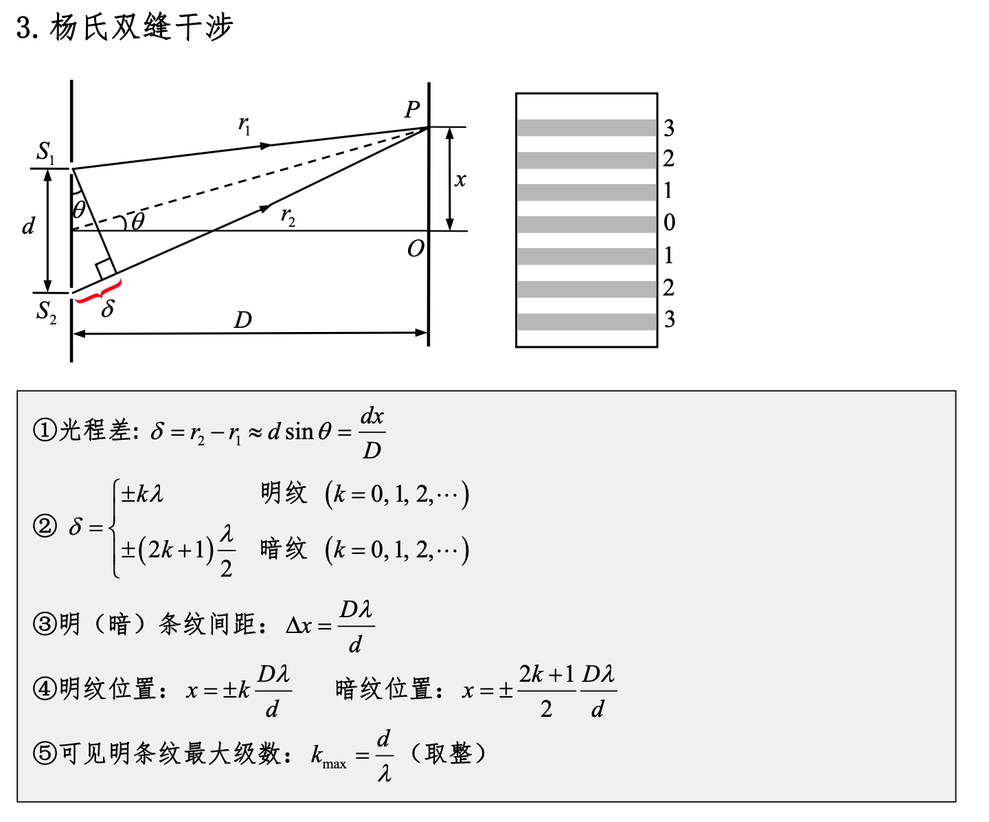
3. What Are the Characteristics of Young's Double-Slit Interference Fringe Distribution?
Young's double-slit interference experiment produces two coherent light beams through two slits, forming interference fringes. Its characteristics include:
-
Fringe spacing: The spacing of interference fringes is related to the wavelength of light and the distance between the two slits. The fringe spacing Δy can be expressed by the following formula:
where:
- λ is the wavelength of light,
- D is the distance from the slits to the screen,
- d is the distance between the two slits.
-
Central bright fringe: The central bright fringe is the brightest and is located directly opposite the midpoint between the two slits.
-
Equally spaced fringes: The fringes are equally spaced bright and dark fringes, alternating.
-
Fringe intensity: The central bright fringe has the greatest intensity, gradually decreasing toward both sides.
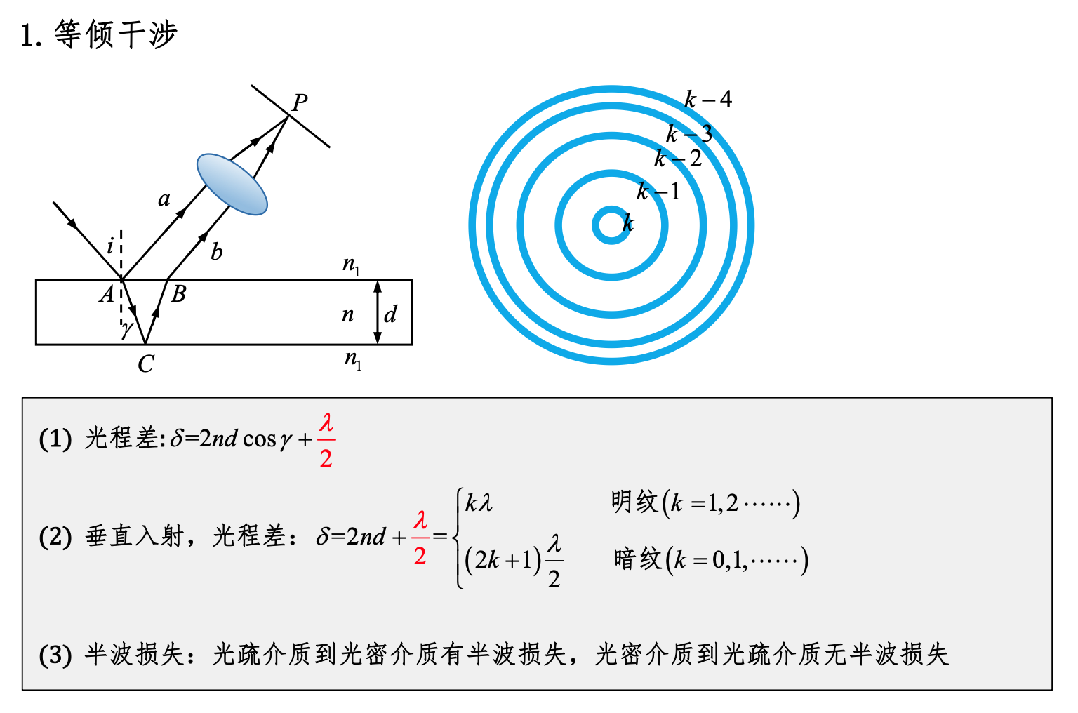
4. What Is Equal Inclination Interference?
Equal Inclination Interference: Equal inclination interference is the interference phenomenon formed when light reflects off a thin film with parallel surfaces (such as soap bubbles or optical thin films). Because the two surfaces of the film are parallel, the incident angles of the reflected light beams are the same, resulting in interference fringes that exhibit equal inclination characteristics.
5. What Are the Characteristics of Equal Inclination Interference Fringes?
The characteristics of equal inclination interference fringes include:
- Concentric rings: The fringes typically appear as concentric rings, with the center being a bright or dark fringe depending on the thickness of the film and the wavelength of light.
- Fringe spacing: The fringe spacing is related to the film thickness and the wavelength of light. The thicker the film, the smaller the fringe spacing.
- Color changes: When illuminated with white light, due to different interference conditions for different wavelengths, the fringes display rainbow-like color changes.
- Symmetry: The fringes are symmetric about the center of the film, and the shape and distribution of the fringes are related to the geometric shape of the film.
These characteristics are determined by the physical process of light reflecting and interfering at the film surfaces.
Week 10 Short Answer Questions
1. What Are Anti-Reflective Coatings and Reflective Coatings?
Anti-reflective coating: An anti-reflective coating is a thin optical coating, usually composed of one or more layers of nanometer-thick transparent materials, applied to the surface of lenses or other optical elements. Its main function is to reduce light reflection at interfaces through interference effects, thereby increasing the intensity of transmitted light. A typical anti-reflective coating design causes the reflected light wave at the film-substrate interface and the reflected light wave at the film surface to cancel each other out (with a phase difference of half a wavelength), thereby reducing reflection.
Reflective coating: A reflective coating increases the reflectivity of light by applying one or more layers of high-reflectivity materials to the surface of optical elements, reducing the intensity of transmitted light. Reflective coatings are commonly used in mirrors, laser cavity mirrors, and other optical elements that require high reflectivity. The design of reflective coatings typically enhances the intensity of reflected light waves through the interference effects of multilayer films.
2. Why Do Camera Lenses Appear Purple-Red?
Camera lenses appear purple-red because the lens surface is coated with an anti-reflective coating. The anti-reflective coating increases the transmittance and imaging quality of the lens by selectively reducing the reflection of certain wavelengths of light and increasing the intensity of transmitted light. Due to the interference effect of the anti-reflective coating, certain wavelengths of light (usually blue and green light) are transmitted more effectively, while other wavelengths (such as red and purple light) are partially reflected, causing the lens to appear purple-red at certain angles.
3. What Is the Difference Between Fraunhofer Diffraction and Fresnel Diffraction?
Fraunhofer Diffraction:
- Occurs under far-field conditions, where the light source and observation screen are sufficiently far away, or light is focused to a distance through a lens.
- The diffraction pattern is the result of interference of parallel light beams, usually observed at the focal plane.
- Mathematical treatment is relatively simple and can be described using Fourier transforms.
Fresnel Diffraction:
- Occurs under near-field conditions, where the light source or observation screen is close to the obstacle.
- The diffraction pattern is the result of interference of spherical waves, and the pattern changes significantly with distance.
- Mathematical treatment is more complex, requiring Fresnel integrals.
4. What Is the Half-Period Zone Method?
The half-period zone method is a method for analyzing light diffraction, especially used to describe the diffraction of circular apertures or circular diaphragms. The wavefront is divided into multiple concentric rings, each with an optical path difference of half a wavelength (i.e., a phase difference of 180 degrees). These rings are called half-period zones. Since the light from adjacent half-period zones has a phase difference of 180 degrees, theoretically every two adjacent half-period zones interfere and cancel each other, affecting the intensity distribution of the diffraction pattern.
5. How Is the Number of Half-Period Zones Determined?
The number of half-period zones depends on the distance from the observation point to the light source or diaphragm and the wavelength of the light. Specifically, the number of half-period zones N can be approximately calculated by the following formula:
where:
- r is the radial distance from the light source to the observation point,
- λ is the wavelength of the light,
- z is the axial distance from the light source to the diaphragm.
6. What Are the Characteristics of Single-Slit Diffraction Fringes?
The characteristics of single-slit diffraction fringes include:
- The central bright fringe is the widest and brightest, with the greatest intensity.
- On both sides of the central bright fringe are alternating dark fringes and narrower bright fringes, with the intensity of bright fringes gradually decreasing.
- The fringe spacing is related to the slit width, wavelength, and observation distance. The narrower the slit, the larger the fringe spacing.
- The positions of bright and dark fringes can be determined by the following formulas:
- Bright fringes (maxima): d sin θ = mλ (where m is an integer)
- Dark fringes (minima): d sin θ = (m + 1/2)λ (where m is an integer)
These characteristics are determined by the wave nature of light and interference effects together.
Week 11 Short Answer Questions
1. What Is the Relationship Between Diffraction Grating and Single-Slit Diffraction?
Single-slit diffraction: Single-slit diffraction occurs when light passes through a single slit. The light wave bends at the edges of the slit, forming a series of alternating bright and dark fringes on the screen. The central fringe is the brightest with the greatest intensity, and the intensity of fringes on both sides gradually decreases.
Diffraction grating: Diffraction grating occurs when light passes through a grating with a large number of parallel slits. Each slit of the grating produces an effect similar to single-slit diffraction, but due to the interference of multiple slits, the diffraction pattern of the grating is more complex and clearer.
Relationship:
- The single-slit diffraction pattern is the basic building block of the grating diffraction pattern. Each slit of the grating produces a single-slit diffraction pattern.
- The positions of grating diffraction fringes are determined by the grating equation, while the intensity distribution is determined by the envelope of single-slit diffraction.
- The positions of the principal maxima of grating diffraction coincide with the maxima of single-slit diffraction, but the grating diffraction fringes are narrower and brighter.
2. What Are Principal Maxima?
Principal maxima: In grating diffraction, principal maxima are bright fringe positions determined by the grating equation. These fringes result from the coherent superposition of light waves from all grating slits in these directions, producing strong interference maxima. The positions of principal maxima are determined by the grating equation:
[ d \sin \theta = m \lambda ]
where:
- d is the grating constant (the distance between two adjacent slits),
- θ is the diffraction angle,
- m is the diffraction order (integer),
- λ is the wavelength of light.
3. What Are Secondary Maxima?
Secondary maxima: Secondary maxima are weaker bright fringes located between the principal maxima in the grating diffraction pattern. These fringes result from the superposition of partially coherent light waves in these directions, but their intensity is much less than that of principal maxima. The positions and intensities of secondary maxima are related to the grating structure and the wavelength of light, but are generally not as prominent as principal maxima.
4. What Are the Characteristics of Grating Diffraction Fringes?
The characteristics of grating diffraction fringes include:
- Fringe positions are determined by the grating equation, and fringe spacing is related to the grating constant and wavelength.
- Principal maxima are very bright and narrow, with intensity decreasing as the diffraction order increases.
- Secondary maxima are weaker and wider, located between principal maxima.
- Fringe spacing is related to the number of slits and slit spacing — the more slits, the sharper the fringes.
5. What Is the Missing Order Phenomenon?
Missing order: The missing order phenomenon occurs when, under certain specific conditions, some diffraction orders of principal maxima in grating diffraction disappear. This usually happens when the relationship between the slit width of the grating and the wavelength of light satisfies specific conditions. The missing order occurs because in these specific directions, the minimum of single-slit diffraction coincides with the position of a principal maximum of grating diffraction, causing that diffraction order to be weakened or completely disappear.
6. What Is the Polarization of Light?
Polarization of light: The polarization of light refers to the vibration direction of the electric field vector of a light wave in the direction of propagation. In unpolarized light, the electric field vector vibrates randomly in all directions, while in polarized light, the electric field vector vibrates in a specific direction. According to the vibration direction of the electric field vector, polarized light can be divided into linearly polarized light, circularly polarized light, and elliptically polarized light.
7. How to Distinguish Polarized Light?
Methods for distinguishing polarized light include:
- Polarizing filter: By observing the change in intensity of light after passing through a polarizing filter, the polarization of light can be determined. When linearly polarized light passes through a polarizing filter, its intensity changes with the rotation angle of the filter, while the intensity of unpolarized light changes less.
- Birefringent material: Through birefringent materials such as calcite crystals, polarized light can be split into two beams with different polarization directions, allowing observation of its polarization.
- Reflection and refraction experiments: Using Brewster's angle phenomenon, when the incident angle equals Brewster's angle, the reflected light is completely polarized.
8. What Is Malus's Law?
Malus's Law: Malus's Law describes the intensity change of linearly polarized light after passing through a polarizer. The law states that when linearly polarized light passes through a polarizing filter, the transmitted light intensity I is related to the incident light intensity I₀ and the angle θ between the polarization direction of the incident light and the transmission axis of the polarizer by:
This means the transmitted light intensity is proportional to the square of the cosine of the angle.
